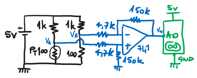
Today in the laboratory I propose to electronics students in the fifth year of secondary school to experiment with a PT100 resistance thermometer. We want to measure the temperature detected with PT100 in the range between 0 and 100 °C and acquire it with Arduino Uno witch ADC has input dynamics between 0 and 5 V.
We use a transducer like the one in the figure, purchased from RS, an important electronics distributor who has shop near my home. Here I report the technical sheet: Platinum Resistance Temperature Sensors.
Conditioning is based on the use of the resistive Wheatstone bridge and the differential amplifier with LM741 or TL081 opamp. These opamps require dual power supply.
We connect the PT100 in 2-wire connection mode and calculate that for measurements in the range between 0 and 100 °C its resistance varies between 100 Ω and 138.5 Ω. We choose the other resistances of the bridge: two of 1 kΩ and one of 100 Ω which serves as a reference for the measurement of the PT100 at 0 °C. In the diagram we report our conditioning. The VB voltage is set at 450 mV as a measurement reference, while the VA voltage detected on the voltage scores with the PT100 can vary between 450 mV and 610 mV.

Our analysis for the Arduino sketch considers that the resistive variations of the PT100 are in the order of mΩ and consequently also the voltage variations measured on the VAB bridge are small (in the order of mV) while on the contrary the floating point calculations performed by Arduino they are poor in resolution (two decimal places); so we prefer to program the calculations in Arduino working in mV, ie translating VO into mV rather than Volt.
// PT100 range 0 - 100 °C using
// Wheatstone bridge and differential
// amplifier with LM741

int pt100;
float Vab, Va, Vo, Rpt100, T;

void setup()
{
  Serial.begin(9600);
}

void loop()
{
 pt100 = analogRead(A0);     // 10 bits code
 Vo = pt100/1024.00*5000.00; // voltage in mV
 Vab = Vo/31.91;    // amplifier gains: 150k/4.7k=31.91
 Va = Vab+454.54;   // bridge reference voltage in mV:
                    // 5V*100/(1k+100)
 Rpt100 = (Va*1000.00)/(5000.00-Va);  // PT100 voltage in mV:
                          // 5V*Rpt100/(1k+Rpt100)
 T = (Rpt100-100)/0.385;  // pt100 transducer relationship:
                          // Rpt100=100*(1+0.00385*T)
 Serial.print("T: ");
 Serial.print(T);
 Serial.print(char(176));
 Serial.println("C");
 delay(1000);
}
And then also a simulation with Tinkercad where the PT100 is simulated with the series of a 100 Ω resistor and a potentiometer set with a maximum of 38.5 Ω: https://www.tinkercad.com/embed/83ENtZz1e8k (in the Tinkercad window, open the code section and activate the serial monitor before starting the simulation to view the temperatures detected when you turn the potentiometer).