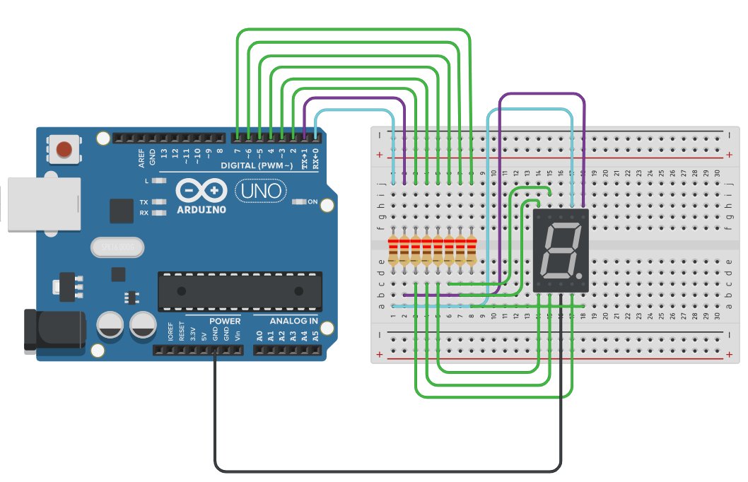
In this example I propose a simple simulation with Tinkercad of a circuit that creates a counter from 0 to 9 with a 7-segment display, programmed using Arduino Uno. The display is of the common cathode type.
The sketch that I propose to you is really working. This is the link: https://www.tinkercad.com/things/6ok3zL0QW2L. It is based on a look-up table made with an array where I have coded the digits of the numbers to be shown on the display.
I used port registers based programming and I choosed the ATMega 328 pin group called port D which is 8 bit and is convenient for managing an LED display. Here you can find information about Arduino port registers: https://www.arduino.cc/en/Reference/PortManipulation.
It is important that when you load the sketch in the Arduino FLASH memory, you momentarily disconnect pins 0 and 1, because they are used by the USB as serial TX and RX, otherwise the loading fails.
This is the sketch:
byte numero [10]={B00111111, B00000110, B01011011, B01001111, B01100110, B01101101, B01111101, B00000111, B01111111, B01101111};
int i=0;
void setup()
{
DDRD = B11111111;
}
void loop()
{
PORTD = numero[i];
delay(500);
i++;
if (i>9)
i=0;
}